Building a Ferrari V-12
Engine Stand

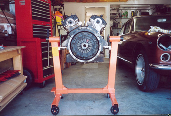
This is a picture of a an original Ferrari engine stand. You can see
them in factory photographs taken in the sixties. Most four mount V-12
Ferrari engines will fit which would include all the road going 250 Engines,
and 330 engines. The late four cam 275 GTB will not fit this stand because
it has one engine mount, but I believe the early two cam engines will work.
Check your particular engine before building this stand.
You will need to do some welding, so you can decide if you want to make
the whole stand from scratch, or if you want to modify an existing stand.
The most important factor is the engine has to be mounted so the flywheel
and water pump is clear to flip the whole engine over.
Scratch building this stand is simply a matter of finding steel tubing
that will fit inside one another to form the pivot point that will support
approximately 500 pounds. Modifying an "American" V-8 stand can be done
using two stands face to face. You cut the center leg off one stand, and
the wheel off the other one, and weld a channel in the stand with the missing
leg so the other stand can slide into the channel. Give yourself two feet
of clearance from the center of the pivot to the bottom of the drip pan,
and you should be ready to go.

Here are some measurements of the support arm with a 330 engine mounted
to the stand. The 12" measurement is so you can roughly guess where the
center of gravity of the engine block will be. I didn't get the distance
between the pivots, but if you're building a stand from scratch, this measurement
can be taken from your engine.

Here's another view of a Ferrari Factory engine stand, if you can see
it through all the clutter! I took some measurements of a type 209 V-12
Engine (my 330 America) and the widths are approximately:
13 inches on the flywheel side
17 inches on the water pump side.
On the engine stand pictured here, the pivots can slide in and out
to make up the differences, but allow for a maximum of 19 inches of width
for the wide mounts. Also notice the slots in support bars allowing for
even more adjustment.
Another idea submitted from Mike:
A friend (& GTE owner) build a husky 4-point-mount adapter for
the 250 engine to mount in a "regular" (but substantial) engine stand,
the type that hangs a V-8 from the transmission end. One would think this
way of mounting a V-12 would prove unwieldy and unstable, but it worked
quite well for me. Price was right, too.
Jonathon Brent built an engine stand using some of the ideas I suggested,
and submitted these pictures and his design. It looks great! Here's what
he wrote:
"Thanks again for the engine stand dimensions. Using those as
the starting point, I was able to make my own using V8 stands and a little
welding. I started by getting two cheap stands that look like this:

These are the 1000lb units sold by Harbor Freight, on sale for $40
each. The important part is the horizontal bar which slides into
a tube at the bottom of the upright, long enough to space the mount plates
far enough apart. Any brand which assembles that way would work.
The dual casters on the short wheel tube across from the mount were a bonus.
The 750lb units were cheaper, but the usable length of the bottom bar was
too short, and it only had one caster.
As you can see, the finished stand used two of the uprights, with the
second simply slipped onto the bottom bar all the way to the end.
I bolted the four castors as far out on the longer wheel tubes as possible,
and put the fixed wheels on only to save my ankles. The second long
wheel tube was drilled/bolted in place where the short one was on the original
stand.

For the 330GT Type 209 engine, the template has the flywheel bolt holes
17 3/16" apart, the middle/forward mounts 14 1/8" apart, the for/aft bolt
spacing 14 1/2", and the center of gravity marked at 12" from the flywheel
bolts. The available space under each engine mount was easily measured
from the engine in the car. The 1" steel rod and 1/2" brackets were
scrap from work, made to fit the assembled stand and template. The
slots and holes in the brackets were ground a bit over 1/2", and one side
of each stand plate was cut off for better access. Combined with
the loose fit of the stand parts, this gave plenty of wiggle room.
For your SF Bay Area viewers, a local welding instructor Jonathan Hyman
(JHTigster@home.com), did a great job of the welding.

The stand pivot tubes were not square when both uprights were assembled
on the single cross tube, so putting the plates in one way or the other
made a big difference to how far apart the flywheel support brackets would
be. Also, we had to assemble the stand onto the engine while it was
in the hoist, as the
center brackets are really longer than they need to be, but it fits
great.
Based on your dimensions, the height and placement of the pivot tubes
worked out very well. The engine is not too top heavy, can be rotated
without hitting the stand, and there is excellent access to all parts of
the engine.

I hope this helps, if there are any questions/comments, feel free to
contact me at jonathon.brent.b@bayer.com
Jon"

Ian Levy sent in pictures of the engine stand he made to hold his
365GTC/4 engine.
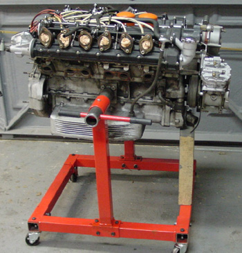
These later Ferrari engines have a single engine mount on either side
of the block. Ferrari started making blocks like this in the late 60s with
275GTBs, and later 330 Engines.

Ian said he had to support the engine with a block of wood to keep
it from turning over with its high center of gravity. I feel maybe removing
the air conditioner compressor could help.