Steering Box Rebuild
Colin Angell, a fellow Ferrari owner rebuilt his ZF gearbox, and shares
what he learned from the experience:
I was getting to the end of a complete overhaul of the front suspension
and steering on my 365 GTC when I realised that I wouldn't really be satisfied
without at least a thorough inspection of the steering box.
Removal of the box is quite straightforward if the upper wishbone is
already out of the car. You simply have to undo the pinch-bolt which fastens
the end of the steering column to the splined end of the worm gear, remove
three nuts holding the chassis mounting block and lever the whole assembly
off.
Unfortunately, try as I might, I could not get the splines to disengage
and I eventually resorted to removing the column as well. It was at this
point that I realised that I had something of a hybrid steering assembly.
The lower end of the column was as 330 GTC but the upper end was as used
on a 365GT 2+2. I suppose with only 21 RHD models made it is not surprising
that there appears to be no defining "standard" system for the steering
box assembly, which is nevertheless based on a well made, tried and tested,
ZF, worm and peg box.
Having removed the box and column from the car it lay on the floor of
my garage for a couple of weeks while I tackled some other aspect of refurbishment.
As it lay there it slowly oozed the most repulsive black grunge from a
small breather hole in the oil filler. There was no question of me just
doing a clean and repaint of the outside. Whatever was inside was much
more important.
With the unit off the car I was still unable to separate the splined
connection and yet with the column attached it was too unwieldy to manage,
so I split the column at the lower universal joint, which I immediately
realised was very floppy and in a terrible state. Fortunately I was able
to replace this with an off the shelf spare from Ferrari UK which came
complete with new fixing socket screws, cross-drilled to take retaining
wire.
Holding the box in a bench vice I set about the reluctant splined joint
which eventually succumbed to a combination of penetrating oil, a little
heat and (I'm ashamed to admit it) a small wedge to open up the split.
Once apart and briskly wire brushed there was no apparent rust or damage
to the splines. I suppose it had just been done up for 34 years and wanted
to stay that way!
Taking the top off the box I was surprised to find that it still contained
a great deal of thick, treacly gear oil and it was a very messy job to
drain it and totally disassemble the innards.
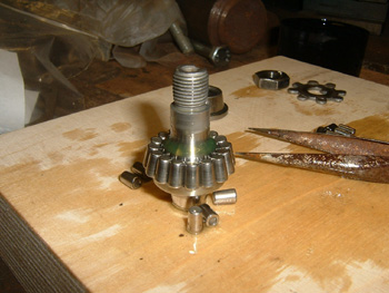
It is somewhat surprising that the ball and tapered roller bearings
are all loose (not held in cages) and I was careful to keep them each in
their individual sets. Once degreased and cleaned I finished by washing
everything in warm soapy water, rinsing and then drying. Following a couple
of hours on a hot tray, to make sure that everything was completely dry
I separated out the components into their sets and dropped them into little
pots filled with clean oil.
A close inspection of the critical items showed no signs for concern.
Amazingly all bearings and bushings were in good condition and apart from
replacing a couple of oil seals, it was just a case of careful reassembly.
To keep the ball bearings in their respective cups during assembly and
disassembly loose fitting metal spring clips were clipped into recesses
in the worm gear shaft. They were very difficult to remove and I had to
grind the tips of an otherwise perfectly good set of circlip pliers to
manage that. Putting them back was even more difficult. In fact it completely
stumped me!
As they serve no purpose other than to keep everything together whilst
the worm is out of the box, I gave up the struggle and substituted a pair
of 25mm x 2.5mm O-rings, which seem to do the job perfectly.

The worm and peg box is a very simple but precise piece of equipment
and the set up is critical for safe, efficient and consistent operation.
The worm should be free to rotate without excessive pressure, but must
have absolutely zero end play. Adjustment is by shimming. The peg must
be free to rotate on its 32 individual tapered rollers with similar accuracy.
I took a great deal of care with these critical items and carried out
test after test over three or four evenings before being satisfied. Even
though I had not changed the bearings, my re-shimming of the worm was 0.04mm
less than when I opened the box up. There must have been end float before!

Assembling the tiny taper rollers was a painstaking business and more
than once I got to almost putting in the last roller, when three or four
others would fall out! Eventually I resorted to smearing the retaining
cups with a little Vaseline to help hold things in place long enough to
allow assembly.
Further evidence of a non-standard set up came when I discovered that
the oil seals supplied by Ferrari did not fit. It turned out that the shaft
and seal housings were imperial sizes, not metric, even though the ends
had been machined down to accept metric fittings and standard splines.

Having painted the outside and reassembled the inside it remained for
me to make a new gasket for the top cover (not available from Ferrari despite
being on order since September 2000!). This was quite easily achieved with
some 0.5mm gasket paper, a scalpel blade and a 9mm hole punch.
Back together again and refilled with EP 140 gear oil I am pleased to
say the steering box operates perfectly and I look forward to sitting behind
the steering wheel once more.

Kerry Chesbro added this paperwork from ZF showing model numbers and
applications for which Ferraris. Click on the image to look at it close
up.
